
 Home
Home

Controlled
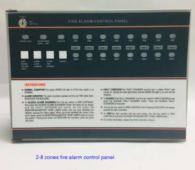
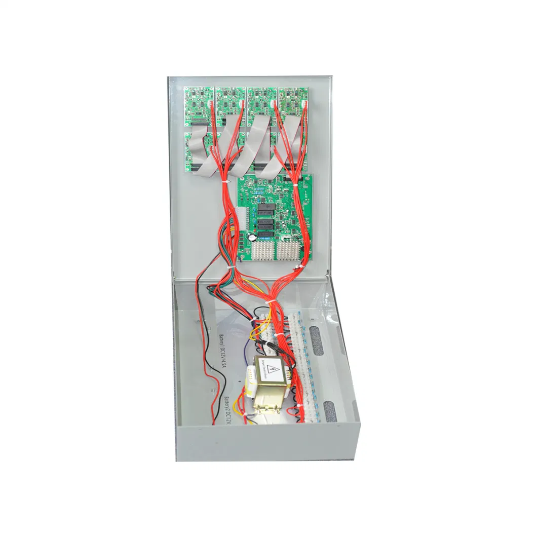
CONTROL PANEL The fire panel must be sited internally, in an area where it is readily accessible by staff on duty and th
Basic Info.
| Model NO. | CP1018 |
| Receive Frequency | 485/232 |
| Wiring Mode | Sub-Line System |
| Number of Zones | 18 |
| Standby Battery | 2*12V |
| Primary AC | 90-270VDC |
| Color | Gray |
| Weight | 5kg |
| Transport Package | Carton |
| Specification | 325x265x100mm |
| Trademark | panel |
| Origin | China |
| HS Code | 8531100000 |
| Production Capacity | 500000/Month |
Product Description
CONTROL PANELThe fire panel must be sited internally, in an area
where it is readily accessible by staff on duty and the
fire brigade. The area should be clean and dry and
you should take into account any likelihood of
tampering or vandalism. The ambient light and
sound levels should allow the status of the indicators
to be clearly seen and the internal sounder to be
heard. Full details can be found in BS 5839: Pt1: 1988:
Section 15.3 "Fire Detection and Alarm Systems for
Buildings".
External (key-switch operated):
- Reset/resound/test zone lamps evacuate
- Silence alarm sounders
- Silence fault sounders
Internal:
- One man detector test
- Zone isolate
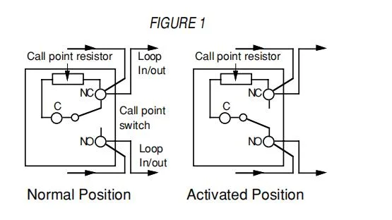
- Revert to short-circuit: fire (no resistors in call points)
External indicators:
- Sounder fault
- Battery/power supply fault
- Mains on
- Zone fire
- Zone fault
Internal indicators:
- Open circuit zone fault
- Short circuit zone fault
- Zone isolated
- Engineer test selected
Outputs:
- Two sounder circuits (alarm relay contacts can be obtained by connecting a relay to a sounder circuit)
Ancillary connections for expansion modules will allow the following:
- Repeater panels
- Multiple sounder outputs
- Connection to landlord panel
Specifications
| 2 (0.8A supply) | 4 / 6 (1.5A supply) | 8/10/12/14/16/18 (4.0A supply) | |
| Power specifications | |||
| Mains supply voltage | 230±10%V AC, 50/60Hz | 230±10%V AC, 50/60Hz | 230±10%V AC 50/60Hz |
| Internal power supply | 27V DC | 27V DC | 27V DC |
| Total output current limited to | 800mA at 240V AC | 1500mA at 240V AC | 4000mA at 240V AC |
| Auxiliary power output | 27V DC | 27V DC | 27V DC |
| Mains supply monitored for failure | Yes | Yes | Yes |
| Battery charger monitored for failure | Yes | Yes | Yes |
| Batteries monitored for disconnection and failure | Yes | Yes | Yes |
| Detector circuit specification | |||
| Number of circuits | 2 | 4 or 6 | 8, 10, 12, 14,16,or 18 |
| Line fault monitored for open circuit | Yes | Yes | Yes |
| Line fault monitored for short circuit | Yes (can be disabled) | Yes (can be disabled) | Yes (can be disabled) |
| Line fault monitored for detector removal | Yes, if end of line monitor unit fitted in place of end of line resistor | ||
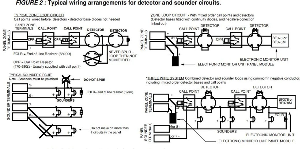
| End of line resistor (supplied) value | 6.8K Ohm, 5% tolerance, 0.25W | 6.8K Ohm, 5% tolerance, 0.25W | 6.8K Ohm, 5% tolerance, 0.25W |
| Detector continuity diodes | Silicone 1N4001 or Schottky type (required if end of line monitor unit fitted to give detector removal fault) | ||
| Call point resistor value (not supplied) | 470 to 680 Ohm, 0.5W | 470 to 680 Ohm, 0.5W | 470 to 680 Ohm, 0.5W |
| Maximum number of smoke detectors per zone | 20 (maximum detector current = 2mA) | 20 (maximum detector current = 2mA) | 20 (maximum detector current = 2mA) |
| Maximum number of manual call points per zone | No limit | No limit | No limit |
| Sounder circuit specifications: | |||
| Number of circuits | 2 | 2 | 2 |
| End of line resistor value | 6.8K Ohm, 5% tolerance, 0.25W | 6.8K Ohm, 5% tolerance, 0.25W | 6.8K Ohm, 5% tolerance, 0.25W |
| Line fault monitored for open circuit | Yes | Yes | Yes |
| Line fault monitored for short circuit | Yes | Yes | Yes |
| Outputs fused at | 1A | 1A | 1.6A |
| Maximum total output current all outputs | 800mA | 1500mA | 4000mA |
| Maximum no of bells at 25mA each bell | 32 | 56 | 120 |
| Maximum no of electronic sounders at 20mA | 40 | 70 | 150 |
| Auxiliary relay contacts (do not connect mains voltages) | 1A 30V DC max voltage free | 1A 31V DC max voltage free | 1A 32V DC max voltage free |
| Fuses-all fuses compliant to ice (EN60127 PT2) | |||
| Mains terminal block | 200mA/T 20mm | 400mA/T 20mm | 630mA/T 20mm |
| Sounder outputs | 1A/F 20mm | 1A/F 20mm | 1.6A/F 20mm |
| Auxiliary output | 1A/F 20mm | 1A/F 20mm | 1A/F 20mm |
| Battery fuse | 1.6A/F 20mm | 1.6A/F 20mm | 3A/F 20mm |
| Door retaining magnets | do not use panel power supply as you will drastically reduce battery standby time | ||
| Connection block | |||
| Largest acceptable | 2.5mm2 | 2.5mm2 | 2.5mm2 |
| Smallest acceptable conductor size | 0.75mm2 | 0.75mm2 | 0.75mm2 |
| Dimensions | |||
| Enclosure (width x height x depth) | 415 x 265 x 100mm | 415 x 265 x 100mm | 415 x 265 x 100mm |
| Weight (without batteries) | 5100g | 5200g | 5500 |
Send to us